Introduction

The audio framework is a whole audio architecture aiming to provide different layers of audio interfaces for applications. The interfaces involve Audio HAL and Audio Framework.

  • Audio HAL: defines unified audio hardware interfaces. It interacts with audio driver to do audio streaming or audio settings.

  • Audio Framework: provides interfaces for audio streaming, and other settings.

The audio framework provides passthrough architecture which supports audio recording, and audio playback. This architecture has no audio mixing, only one audio playback is allowed at the same moment.

The audio interfaces and the entire implementation of audio passthrough architecture is shown below.

../../../_images/audio_passthrough_overview.svg

Audio passthrough overview

The whole audio passthrough architecture includes the following sub-modules:

  • Application Interface

    • RTAudioTrack provides interfaces to play sound.

    • RTAudioRecord provides interfaces to capture sound.

    • RTAudioControl provides interfaces to control sound volumes and so on.

  • Audio HAL

    • AudioHwManager provides interfaces that manage audio cards through a specific card driver program opened based on the given audio card descriptor.

    • AudioHwCard provides interfaces that manage audio card capabilities, including initializing ports, creating stream out and stream in.

    • AudioHwControl provides interfaces for RTAudioControl, and set commands to audio driver.

    • AudioHwStreamOut provides interfaces that get data from the upper layer and render data to audio driver user interfaces.

    • AudioHwStreamIn provides interfaces to capture data from audio driver user interfaces and deliver the data to the upper layer.

  • Audio Driver

    • AUDIO_SP provides interfaces to configure audio sports.

    • AUDIO_CODEC provides interfaces to configure audio codec.

Terminology

The meanings of some widely-used audio terms in this chapter are listed below.

Terms

Introduction

PCM

Pulse Code Modulation, audio data is a raw stream.

channel

A channel sound is an independent audio signal captured or played in different positions, so the number of

channels is the number of sound sources.

mono

Mono means only one single channel sound.

stereo

Stereo means two channels.

bit depth

Bit depth represents the bits effectively used in the process of audio signals.

Sampling depth shows the resolution of the sound. The larger the value, the higher the resolution.

sample

Representing the audio processing at a point in time.

sample rate

The audio sampling rate refers to the number of frames that the signal is sampled per second.

The higher the sampling frequency, the higher quality the sound will be.

frame

A frame is a sound unit whose length is the sample length multiplies the number of channels.

gain

Audio signal gain control to adjust the signal level.

interleaved

It is a recording method of audio data. In the interleaved mode, the data is stored in a continuous manner,

all the channels of sample of first frame are first stored, and then the storage of second frame.

latency

Time delay when a signal passes through the whole system.

overrun

The buffer is too full to let buffer producer write more data.

underrun

The buffer producer is too slow to write data to the buffer so that the buffer is empty when the consumer

wants to consume data.

xrun

Overrun or underrun.

volume

Volume, sound intensity and loudness.

hardware volume

The volume of audio codec.

software volume

The volume set in software algorithm.

resample

Convert the sample rate.

reformat

Convert the bit depth of the sample.

mix

Mix several audio streaming together. Users can hear several audio streaming playing together.

Audio codec

The DAC and ADC controller inside the chip.

Data Format

This section describes the data format that audio framework and audio HAL supports. The common part of audio framework and audio HAL is described here. And the different parts will be described in their own sections.

Both audio framework and audio HAL support interleaved streaming data.

The interleaved data is illustrated in the following figures.

../../../_images/audio_two_channels_interleaved.svg

Two-channel interleaved

../../../_images/audio_four_channels_interleaved.svg

Four-channel interleaved

Framework Format

This section describes the format that Audio Framework supports. Before playback, or capture, make sure your sound format is supported.

Audio Framework has the following types of bit depth:

  • RTAUDIO_FORMAT_INVALID - invalid bit depth of audio stream

  • RTAUDIO_FORMAT_PCM_8_BIT - audio stream has 8-bit depth

  • RTAUDIO_FORMAT_PCM_16_BIT - audio stream has 16-bit depth

  • RTAUDIO_FORMAT_PCM_32_BIT - audio stream has 32-bit depth

  • RTAUDIO_FORMAT_PCM_FLOAT - audio stream has 32-bit float format

  • RTAUDIO_FORMAT_PCM_24_BIT - audio stream has 24-bit depth

  • RTAUDIO_FORMAT_PCM_8_24_BIT - audio stream has 24-bit + 8-bit depth

The following table describes the supported formats for playback and recording. Y means the format is supported; N means the format is not supported.

Bit depth

Playback

Capture

RTAUDIO_FORMAT_PCM_8_BIT

Y

Y

RTAUDIO_FORMAT_PCM_16_BIT

Y

Y

RTAUDIO_FORMAT_PCM_32_BIT

Y

Y

RTAUDIO_FORMAT_PCM_FLOAT

N

N

RTAUDIO_FORMAT_PCM_24_BIT

Y

Y

RTAUDIO_FORMAT_PCM_8_24_BIT

Y

Y

The sample rate is another important format of audio streaming. For playback and recording, audio framework supports the following sample rates. Y means the sample rate is supported; N means the sample rate is not supported.

Sample rate

Playback

Capture

8000

Y

Y

11025

Y

Y

16000

Y

Y

22050

Y

Y

32000

Y

Y

44100

Y

Y

48000

Y

Y

88200

Y

Y

96000

Y

Y

192000

Y

Y

To do audio streaming, the channel count parameter setting is necessary, too. For playback and recording, audio framework supports the following channel counts. Y means the channel count is supported; N means the channel count is not supported.

Channel count

Playback

Capture

1

Y

Y

2

Y

Y

4

Y

Y

6

Y

Y

8

Y

Y

HAL Format

Audio Hal has the following types of bit depth:

  • AUDIO_HW_FORMAT_INVALID - invalid bit depth of audio stream

  • AUDIO_HW_FORMAT_PCM_8_BIT - audio stream has 8-bit depth

  • AUDIO_HW_FORMAT_PCM_16_BIT - audio stream has 16-bit depth

  • AUDIO_HW_FORMAT_PCM_32_BIT - audio stream has 32-bit depth

  • AUDIO_HW_FORMAT_PCM_FLOAT - audio stream has 32-bit float format

  • AUDIO_HW_FORMAT_PCM_24_BIT - audio stream has 24-bit depth

  • AUDIO_HW_FORMAT_PCM_8_24_BIT - audio stream has 24-bit + 8-bit depth

If using the Audio HAL interface, check the bit depth HAL supported for Playback and Capture. Y means the format is supported; N means the format is not supported.

Bit depth

Playback

Capture

AUDIO_HW_FORMAT_PCM_8_BIT

Y

Y

AUDIO_HW_FORMAT_PCM_16_BIT

Y

Y

AUDIO_HW_FORMAT_PCM_32_BIT

Y

Y

AUDIO_HW_FORMAT_PCM_FLOAT

N

N

AUDIO_HW_FORMAT_PCM_24_BIT

N

N

AUDIO_HW_FORMAT_PCM_8_24_BIT

Y

Y

The sample rate is another important format of HAL audio streaming. For playback and recording, audio HAL supports the following sample rates. Y means the sample rate is supported; N means the sample rate is not supported.

Sample rate

Playback

Capture

8000

Y

Y

11025

Y

Y

16000

Y

Y

22050

Y

Y

32000

Y

Y

44100

Y

Y

48000

Y

Y

88200

Y

Y

96000

Y

Y

192000

Y

Y

To do audio streaming, the channel count parameter setting is necessary, too. For playback and recording, audio HAL supports the following channel counts. Y means the channel count is supported; N means the channel count is not supported.

Channel count

Playback

Capture

1

Y

Y

2

Y

Y

4

Y

Y

6

Y

Y

8

Y

Y

Architecture

Playback Architecture

The block diagram of audio playback architecture is shown below.

../../../_images/audio_playback_architecture.svg

Playback architecture

The audio playback architecture includes the following sub-modules:

  • Audio Framework: provides interfaces for applications.

  • Audio HAL: gets playback data from audio framework, and sends the data to audio driver.

  • Audio Driver: gets playback data from audio HAL and sends data to audio hardware.

Record Architecture

The block diagram of audio record architecture is shown below.

../../../_images/audio_record_architecture.svg

Record architecture

The audio record architecture includes the following sub-modules:

  • RTAudioRecord: captures data from Audio HAL, and provides data to audio applications, which want to record data.

  • Audio HAL: gets record data from Audio driver, and sends the data to RTAudioRecord.

  • Audio Driver: gets record data from Audio hardware, and sends data to audio HAL.

Control Architecture

The block diagram of audio control architecture is shown below.

../../../_images/audio_control_architecture.svg

Control architecture

The audio control architecture includes the following sub-modules:

  • RTAudioControl: called by Apps, and interacts with HAL to do audio control settings.

  • Audio HAL: does audio control settings by calling Driver APIs.

  • Audio Driver: controls audio codec hardware.

Configurations

HAL Configuration

Audio hardware configurations lie in {SDK}/component/soc/amebadplus/usrcfg/include/ameba_audio_hw_usrcfg.h.

Different boards have different configurations. For example, some boards need to use an amplifier, while others do not. Different boards may use different pins to enable the amplifier; the start-up time is different for different amplifiers. In addition, the pins used by each board’s DMICs may be different, and the stable time of DMICs may be different. All the information needs to be configured in the configuration file.

The ameba_audio_hw_usrcfg.h file has the description for each configuration, please set them according to the description.

Interfaces

The audio component provides two layers of interfaces.

Interface layers

Introduction

Audio Driver Interfaces

Audio Hardware Interfaces.

Audio HAL Interfaces

Audio Hardware Abstraction Layer Interfaces.

Audio Framework Interfaces

High-level Interfaces for applications to render/capture stream, set volume and so on.

The interfaces layer is shown below.

../../../_images/audio_interfaces.svg

Audio interfaces

Driver Interfaces

Audio Clock and Function APIs

API

Introduction

RCC_PeriphClockCmd

Enable or disable the APB peripheral clock and function

RCC_PeriphClockSource_SPORT

Configure SPORT clock

SPORT APIs

API

Introduction

AUDIO_SP_StructInit

Fill each SP_StructInit member with its default value

AUDIO_SP_Register

Register audio SPORT with its index, direction, and SP_StructInit members.

AUDIO_SP_Unregister

Unregister audio SPORT with its index

AUDIO_SP_Reset

Reset SPORT module

AUDIO_SP_GetTXChnLen

Get audio SPORT Tx channel length

AUDIO_SP_GetRXChnLen

Get audio SPORT Rx channel length

AUDIO_SP_SetTXClkDiv

Set audio SPORT Tx BCLK divider factor

AUDIO_SP_SetRXClkDiv

Set audio SPORT Rx BCLK divider factor

AUDIO_SP_SetMclk

Set audio SPORT MCLK enable or disable

AUDIO_SP_SetMclkDiv

Set audio SPORT MCLK divider factor

AUDIO_SP_SetFixBclk

Set audio SPORT fixed BLCK mode

AUDIO_SP_SelFixBclk

Select audio SPORT BCLK divider factor

AUDIO_SP_TXCHNSrcSel

Select audio SPORT Tx channel source

AUDIO_SP_RXFIFOSrcSel

Select audio SPORT Rx FIFO source

AUDIO_SP_TXSetFifo

Set audio SPORT TX FIFO enable or disable

AUDIO_SP_RXSetFifo

Set audio SPORT RX FIFO enable or disable

AUDIO_SP_Init

Initialize the audio SPORT registers according to the specified parameters in SP_InitStruct

AUDIO_SP_TXStart

Start or stop SPORT Tx path

AUDIO_SP_RXStart

Start or stop SPORT Rx path

AUDIO_SP_DmaCmd

SPORT and GDMA handshake on or off

AUDIO_SP_SetSelfLPBK

Set SPORT self-loopback mode

AUDIO_SP_SetTXWordLen

Set audio SPORT Tx word length

AUDIO_SP_SetRXWordLen

Set audio SPORT Rx word length

AUDIO_SP_GetTXWordLen

Get audio SPORT Tx word length

AUDIO_SP_GetRXWordLen

Get audio SPORT Rx word length

AUDIO_SP_SetMonoStereo

Set the audio SPORT channel number

AUDIO_SP_SetMasterSlave

Set the audio SPORT master or slave mode

AUDIO_SP_TXGDMA_Init

Initialize GDMA peripheral single block mode for sending data

AUDIO_SP_RXGDMA_Init

Initialize GDMA peripheral single block mode for receiving data

AUDIO_SP_TXGDMA_Restart

Audio GDMA TX restart in isr

AUDIO_SP_RXGDMA_Restart

Audio GDMA RX restart in isr

AUDIO_SP_LLPTXGDMA_Init

Initialize Link-list mode GDMA peripheral for Tx data

AUDIO_SP_LLPRXGDMA_Init

Initialize Link-list mode GDMA peripheral for Rx data

AUDIO_SP_SetTXCounter

Enable or disable SPORT TX counter interrupt

AUDIO_SP_SetTXCounterCompVal

Set SPORT Tx counter compare value

AUDIO_SP_ClearTXCounterIrq

Clear SPORT Tx counter IRQ

AUDIO_SP_SetPhaseLatch

Set SPORT phase latch

AUDIO_SP_GetTXCounterVal

Get SPORT Tx counter value

AUDIO_SP_GetTXPhaseVal

Get SPORT Tx phase value when channel length is 32bit, none of the other bits will do

AUDIO_SP_SetRXCounter

Enable or disable SPORT RX counter interrupt

AUDIO_SP_SetRXCounterCompVal

Set SPORT Rx counter compare value

AUDIO_SP_ClearRXCounterIrq

Clear SPORT Rx counter IRQ

AUDIO_SP_GetRXCounterVal

Get SPORT Rx counter value

AUDIO_SP_GetRXPhaseVal

Get SPORT RX phase when channel length is 32bit, none of the other bits will do

AUDIO_SP_SetDirectOutMode

Set SPORT directout mode

AUDIO_SP_Deinit

De-initialize the audio SPORT index and direction

AUDIO_SP_SetPinMux

Set the AUDIO SPORT pinmux function mux: dout or din

Codec APIs

API

Introduction

AUDIO_CODEC_SetAudioIP

Enable or disable audio codec IP

AUDIO_CODEC_SetI2SIP

Enable or disable I2S IP

AUDIO_CODEC_SetI2SSRC

Select I2S master source.

AUDIO_CODEC_SetI2SRXTDM

Select I2S Rx and I2S Rx TDM mode

AUDIO_CODEC_I2S_StructInit

Default I2S initialization parameter

AUDIO_CODEC_SetI2SParameters

Set I2S initialization parameter

AUDIO_CODEC_SetADCSRSrc

Select ADC sample rate and source, all ADC share source and sample rate

AUDIO_CODEC_EnableADC

Enable or disable per AD and AD FIFO channel clock

AUDIO_CODEC_SetADCVolume

Set the gain of ADC digital volume

AUDIO_CODEC_SetADCHPF

Set per ADC channel HPF mode and select HPF FC

AUDIO_CODEC_SetADCASRC

Set ADC ASRC mode

AUDIO_CODEC_SetADCMute

Mute ADC path

AUDIO_CODEC_SetADCMixMute

Set per ADC mix mute AD input path to mute or unmute

AUDIO_CODEC_SetADCDmicFilter

Enable per DIMC channel filter clock

AUDIO_CODEC_SetDmicClk

Enable and select DMIC clock

AUDIO_CODEC_SetDmicSrc

Select DMIC input ADC channel

AUDIO_CODEC_SetADCEQClk

Enable or disable ADC channel EQ clock

AUDIO_CODEC_SetADCEQFilter

Set EQ band as filter for DMIC Rx

AUDIO_CODEC_SetADCEQBand

Enable or disable ADC channel EQ band

AUDIO_CODEC_SetADCZDET

Set ADC path zero detection function

AUDIO_CODEC_SetADCZDETTimeOut

Set ADC path zero detection time out

AUDIO_CODEC_Record

Audio codec record flow for test

I2S PLL APIs

API

Introduction

PLL_I2S0_CLK

I2S0 CPU PLL CLOCK choose when system clock is an integer multiple of 98.304M or 45.1584M

PLL_I2S1_CLK

I2S1 CPU PLL CLOCK choose when system clock is an integer multiple of 98.304M or 45.1584M

PLL_I2S0_CLK_Auto

I2S0 CPU PLL CLOCK auto choose when system clock is not an integer multiple of 98.304M

or 45.1584M

PLL_I2S1_CLK_Auto

I2S1 CPU PLL CLOCK auto choose when system clock is not an integer multiple of 98.304M

or 45.1584M

PLL_I2S_CLKGet

Get 98.304M or 45.1584M

PLL_I2S_98P304M_ClkTune

I2S PLL output adjust by ppm when system clock is an integer multiple of 98.304M

PLL_I2S_45P1584M_ClkTune

I2S PLL output adjust by ppm when system clock is an integer multiple of 45.1584M

There are two ways to generate I2S PLL: - One is that the system clock is an integer multiple of 98.304M or 45.1584M, we add the system clock in SocClk_Info array, so you can modify the index of SocClk_Info array in bootloader_km4.c. When you need high-quality audio applications, you can use this method.

  • The other is that the system clock is not an integer multiple of 98.304M or 45.1584M, in this case, we automatically get the 98.304M or 45.1584M.

The details are shown in the following figure.

../../../_images/audio_i2s_pll_interfaces.svg

Flow of using I2S PLL interfaces

HAL Interfaces

Audio HAL provides AudioHwStreamOut/AudioHwStreamIn/AudioHwControl interfaces to interact with audio hardware. The interfaces lie in {SDK}/component/audio/interfaces/hardware/audio. The interfaces have specific descriptions in them, read them before use.

  • AudioHwStreamOut: receives PCM data from the upper layer, writes data via audio driver to send PCM data to hardware, and provides information about audio output hardware driver.

  • AudioHwStreamIn: receives PCM data via audio driver and sends to the upper layer.

  • AudioHwControl: receives control calling from the upper layer, and sets control information to the driver.

The AudioHwStreamOut/AudioHwStreamIn is managed by AudioHwCard interface. It is responsible for creating/destroying AudioHwStreamOut/AudioHwStreamIn instance. AudioHwCard is a physical or virtual hardware to process audio stream. It contains a set of ports and devices as shown in following figure.

  • Port – the stream output/input of the audio card is called “port”.

  • Device – The device output/input of audio card is called device.

../../../_images/audio_hal_architecture.svg

AudioHwCard example

The AudioHwManager manages system’s all AudioHwCards and opens a specific card driver based on the given audio card descriptor.

Using AudioHwStreamOut

Users can check the example of AudioHwStreamOut in {SDK}/component/example/audio/audio_hal_render.

Here is the description showing how to use audio HAL interfaces to play audio raw data (PCM format):

  1. Use CreateAudioHwManager() to get AudioHwManager instance:

    struct AudioHwManager *audio_manager = CreateAudioHwManager();
    
  2. Use GetCards() to get all audio card descriptors:

    int32_t cards_size = audio_manager->GetCardsCount(audio_manager);
    struct AudioHwCardDescriptor *card_descs = audio_manager->GetCards(audio_manager);
    
  3. Choose a specific card to play (currently audio manager only support primary audio card):

    struct AudioHwCardDescriptor *audio_card_desc;
    for (int32_t index = 0; index < cards_size; index++) {
       struct AudioHwCardDescriptor *desc = &card_descs[index];
       for (uint32_t port = 0; (desc != NULL && port < desc->port_num); port++) {
          printf("check for audio port \n");
          if (desc->ports[port].role == AUDIO_HW_PORT_ROLE_OUT &&
             (audio_card = audio_manager->OpenCard(audio_manager, desc))) {
             audio_port = desc->ports[port];
             audio_card_desc = desc;
             break;
          }
       }
    }
    
  4. Create AudioHwConfig according to the sample rate, channel, format, and AudioHwPathDescriptor, then use CreateStreamOut() to create an AudioHwStreamOut based on the specific audio card:

    struct AudioHwConfig audio_config;
    audio_config.sample_rate = 48000;
    audio_config.channel_count = 2;
    audio_config.format = AUDIO_HW_FORMAT_PCM_16_BIT;
    struct AudioHwPathDescriptor path_desc;
    path_desc.port_index = audio_port.port_index;
    path_desc.devices = AUDIO_HW_DEVICE_OUT_SPEAKER;
    path_desc.flags = AUDIO_HW_INPUT_FLAG_NONE;
    audio_stream_out = audio_card->CreateStreamOut(audio_card, &path_desc, &audio_config);
    
  5. Write PCM data to AudioHwStreamOut repeatly. Buffer size written can be defined by users. Users need to make sure the size/frame_size is integer.

    int32_t bytes = audio_stream_out->Write(audio_stream_out, buffer, size, true);
    
  6. Use DestroyStreamOut() to close AudioHwStreamOut when finishing playing:

    audio_card->DestroyStreamOut(audio_card, audio_stream_out);
    
  7. Use CloseCard() to destroy the AudioHwCard and finally call DestoryAudioHwManager to release AudioHwManager instance:

    audio_manager->CloseCard(audio_manager, audio_card, audio_card_desc);
    DestoryAudioHwManager(audio_manager);
    

Using AudioHwStreamIn

Users can check the example of AudioHwStreamOut in {SDK}/component/example/audio/audio_hal_capture.

Here is the description showing how to use audio HAL interfaces to capture audio raw data:

  1. Use CreateAudioHwManager() to get AudioHwManager instance:

    struct AudioHwManager *audio_manager = CreateAudioHwManager();
    
  2. Use GetCards() to get all audio card descriptors:

    int32_t cards_size = audio_manager->GetCardsCount(audio_manager);
    struct AudioHwCardDescriptor *card_descs = audio_manager->GetCards(audio_manager);
    
  3. Choose a specific card to capture (currently audio manager only support primary audio card):

    struct AudioHwCardDescriptor *audio_card_in_desc = NULL;
    for (int32_t index = 0; index < cards_size; index++) {
       struct AudioHwCardDescriptor *desc = &card_descs[index];
       for (uint32_t port = 0; (desc != NULL && port < desc->port_num); port++) {
          if (desc->ports[port].role == AUDIO_HW_PORT_ROLE_IN &&
             (audio_card_in = audio_manager->OpenCard(audio_manager, desc))) {
             audio_port_in = desc->ports[port];
             audio_card_in_desc = desc;
             break;
          }
       }
    }
    
  4. Construct AudioHwConfig according to the sample rate, channel, format, and AudioHwPathDescriptor, then use CreateStreamIn() to create an AudioHwStreamIn based on the specific audio card:

    struct AudioHwConfig audio_config;
    audio_config.sample_rate = 48000;
    audio_config.channel_count = 2;
    audio_config.format = AUDIO_HW_FORMAT_PCM_16_BIT;
    struct AudioHwPathDescriptor path_desc_in;
    path_desc_in.port_index = audio_port_in.port_index;
    path_desc_in.devices = AUDIO_HW_DEVICE_IN_MIC;
    path_desc_in.flags = AUDIO_HW_INPUT_FLAG_NONE;
    audio_stream_in = audio_card_in->CreateStreamIn(audio_card_in, &path_desc_in, &audio_config);
    
  5. Read PCM data from AudioHwStreamIn repeatly. This size can be defined by users. Users need to make sure the size/frame_size is integer.

    audio_stream_in->Read(audio_stream_in, buffer, size);
    
  6. Use DestroyStreamIn() to close AudioHwStreamIn when finishing recording:

    audio_card_in->DestroyStreamIn(audio_card_in, audio_stream_in);
    
  7. Use CloseCard() to destroy the AudioHwCard, and finally call DestoryAudioHwManager() to release AudioHwManager instance.

    audio_manager->CloseCard(audio_manager, audio_card_in, audio_card_in_desc);
    DestoryAudioHwManager(audio_manager);
    

Using AudioHwControl

Here is an example showing how to use audio HAL interfaces to control audio codec:

AudioHwCotrol is always thread-safe, and the calling is convenient. To use AudioHwCotrol, the first parameter of the function call should always be GetAudioHwControl(). Take the PLL clock setting for example:

GetAudioHwControl()->AdjustPLLClock(GetAudioHwControl(), rate, ppm, action);

Framework Interfaces

Streaming Interfaces

Audio Streaming Interfaces include RTAudioTrack and RTAudioRecord interfaces. The interfaces lie in {SDK}/component/audio/interfaces/audio. The interfaces have specific descriptions in them, please read them before using.

  • RTAudioTrack: initializes the format of playback data streaming in the framework, receives PCM data from the application, and writes data to Audio HAL.

  • RTAudioRecord: initializes the format of record data streaming in the framework, receives PCM data from Audio HAL, and sends data to applications.

Using RTAudioTrack

RTAudioTrack includes support for playing variety of common audio raw format types so that audio can be easily integrated into applications.

Audio Framework has the following audio playback category types. Applications can use the types to initialize RTAudioTrack. Framework gets the category type and does the volume mixing according to the types.

  • RTAUDIO_CATEGORY_MEDIA - if the application wants to play music, then its type is RTAUDIO_CATEGORY_MEDIA, it can use this type to init RTAudioTrack. Then audio framework will know its type, and mix it with media’s volume.

  • RTAUDIO_CATEGORY_COMMUNICATION - if the application wants to start a phone call, it can output the phone call’s sound, the sound’s type should be RTAUDIO_CATEGORY_COMMUNICATION.

  • RTAUDIO_CATEGORY_SPEECH - if the application wants to do voice recognition, and output the speech sound.

  • RTAUDIO_CATEGORY_BEEP - if the sound is key tone, or other beep sound, then its type is RTAUDIO_CATEGORY_BEEP.

The test demo of RTAudioTrack lies in {SDK}/component/example/audio/audio_track.

Here is an example showing how to play audio raw data:

  1. Before using RTAudioTrack, RTAudioService should be initialized:

    RTAudioService_Init();
    
  2. To use RTAudioTrack to play a sound, create it:

    struct RTAudioTrack* audio_track = RTAudioTrack_Create();
    

    Apps can use the Audio Configs API to provide detailed audio information about a specific audio playback source, including stream type (type of playback source), format, number of channels, sample rate, and RTAudioTrack ringbuffer size. The syntax is as follows:

    typedef struct {
    uint32_t category_type;
    uint32_t sample_rate;
    uint32_t channel_count;
    uint32_t format;
    uint32_t buffer_bytes;
    } RTAudioTrackConfig;
    

    Where

    category_type:

    define the stream type of the playback data source.

    sample_rate:

    playback source raw data’s rate.

    channel_count:

    playback source raw data’s channel number.

    format:

    playback source raw data’s bit depth.

    buffer_bytes:

    ringbuffer size for RTAudioTrack to avoid xrun.

    Note

    The buffer_bytes in RTAudioTrackConfig is very important. The buffer size should always be more than the minimum buffer size Audio framework calculated. Otherwise overrun will occur.

    Use the interface to get minimum RTAudioTrack buffer bytes, and use it as a reference to define RTAudioTrack buffer size, for example, you can use minimum buffer size*4 as buffer size. The bigger size you use, the smoother playing you will get, yet it may cause more latency. It’s your choice to define the size.

    int track_buf_size = RTAudioTrack_GetMinBufferBytes(audio_track, type, rate, format, channels) * 4;
    
  1. Use this buffer size and other audio parameters to create RTAudioTrackConfig object, here’s an example:

    RTAudioTrackConfig track_config;
    track_config.category_type = RTAUDIO_CATEGORY_MEDIA;
    track_config.sample_rate = rate;
    track_config.format = format;
    track_config.buffer_bytes = track_buf_size;
    track_config.channel_count = channel_count;
    

    With RTAudioTrackConfig object, we can initialize RTAudioTrack. In this step, a ringbuffer will be created according to the buffer bytes.

    RTAudioTrack_Init(audio_track, &track_config);
    
  2. When all the preparations are completed, start RTAudioTrack and check if starts success.

    if(RTAudioTrack_Start(audio_track) != 0){
    //track start fail
    }
    
  3. Write audio data to the framework. The write_size can be defined by users. Users need to make sure the write_size/frame_size is integer.

    RTAudioTrack_Write(audio_track, buffer, write_size, true);
    
  4. If users want to pause, stop writing data, and then call the following APIs to tell the framework to do pause:

    RTAudioTrack_Pause(audio_track);
    RTAudioTrack_Flush(audio_track);
    
  5. If users want to stop playing audio, stop writing data, and then call RTAudioTrack_Stop() API:

    RTAudioTrack_Stop(audio_track);
    
  6. Delete audio_track pointer when it’s no use.

    RTAudioTrack_Destroy(audio_track);
    

Using RTAudioRecord

RTAudioRecord supports variety of common audio raw format types, so that you can easily integrate record into applications.

RTAudioRecord supports the following audio input sources:

  • RTDEVICE_IN_MIC - if the application wants to capture data from microphone, then choose this input source.

  • RTDEVICE_IN_HS_MIC- if the application wants to capture data from headset microphone, then choose this input source.

  • RTDEVICE_IN_HS_MIC- if the application wants to capture data from LINE-IN, then choose this input source.

The test demo of RTAudioRecord lies in {SDK}/component/example/audio/audio_record.

Here is an example showing how to record audio raw data:

  1. Create RTAudioRecord first:

    struct RTAudioRecord *audio_record = RTAudioRecord_Create();
    
  2. Apps can use the Audio Configs API to provide detailed audio information about a specific audio record source, including record device source, format, number of channels, and sample rate. The syntax is as follows:

    typedef struct {
    uint32_t sample_rate;
    uint32_t channel_count;
    uint32_t format;
    uint32_t device;
    uint32_t buffer_bytes;
    } RTAudioRecordConfig;
    

    Where

    sample_rate:

    record source raw data’s rate.

    channel_count:

    record source raw data’s channel number.

    format:

    record source raw data’s bit depth.

    device:

    audio input device source for data record.

    buffer_bytes:

    audio buffer bytes in framework. Set 0 to use default value. User can also set other value, the bigger buffer_bytes means bigger latency.

    Here’s an example showing how to create RTAudioRecordConfig object of RTAudioRecord:

    RTAudioRecordConfig record_config;
    record_config.sample_rate = rate;
    record_config.format = RTAUDIO_FORMAT_PCM_16_BIT;
    record_config.channel_count = channels;
    record_config.device = RTDEVICE_IN_MIC;
    record_config.buffer_bytes = 0;
    

    With RTAudioRecordConfig object created, you can initialize RTAudioRecord, in this step, Audio HAL’s AudioHwCard will be opened, according to the audio input device source:

    RTAudioRecord_Init(audio_record, &record_config);
    
  3. When all the preparations are completed, start audio_record:

    RTAudioRecord_Start(audio_record);
    
  4. Read audio microphone data. The read size can be defined by users. Users need to make sure size/frame_size is integer.

    RTAudioRecord_Read(audio_record, buffer, size, true);
    
  5. When the record ends, stop the record:

    RTAudioRecord_Stop(audio_record);
    
  6. When audio_record no use, destroy it to avoid memory leak:

    RTAudioRecord_Destroy(audio_record);
    

Control Interfaces

Audio Control Interfaces include RTAudioControl interfaces to interact with audio control HAL. RTAudioControl provides interfaces to set and get hardware volume, set output device, and so on. The interfaces lie in {SDK}/component/audio/interfaces/audio/audio_control.h. The interfaces have specific descriptions, read them before use.

Using RTAudioControl

Here is an example of how to use RTAudioControl:

  1. Call RTAudioControl to set audio PLL clock 2 ppms slower:

    RTAudioControl_AdjustPLLClock(48000, 2, RTAUDIO_PLL_SLOWER);
    

Audio Hardware Application

DMIC-in

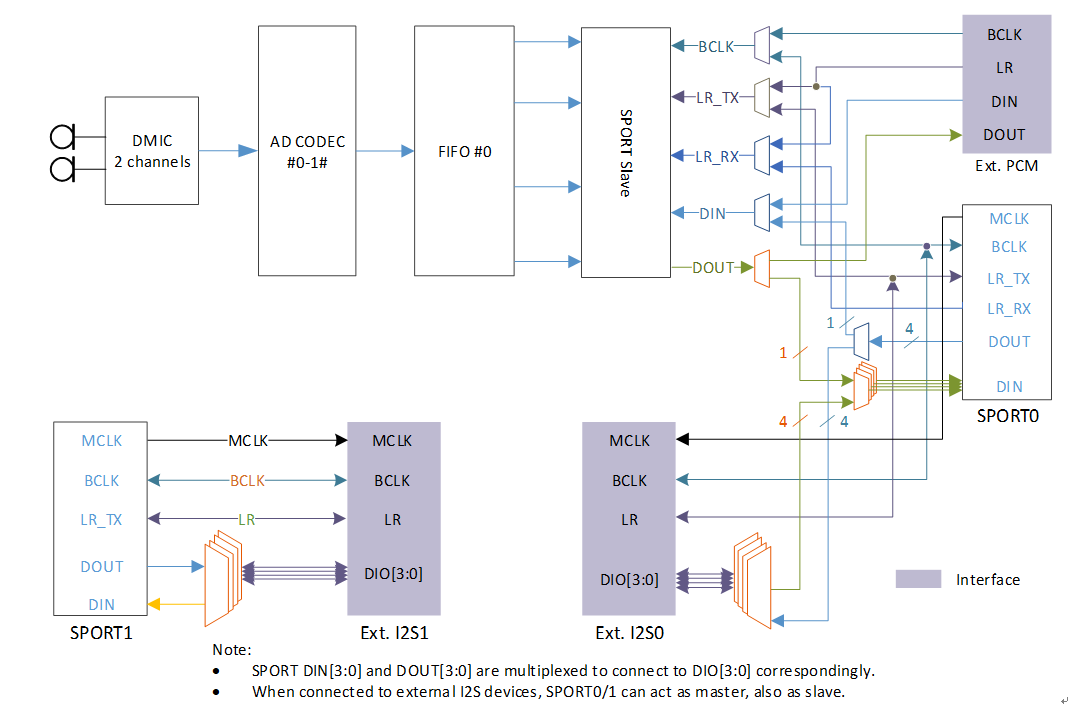
Digital microphone (DMIC) records audio data. It is integrated with ADC internal, and can directly output digital signal. DMIC-in supports mono mode and stereo mode.

DMIC-in Mono Mode

Tie the L/R of a digital microphone to ground or VDD if only one digital microphone is placed.

../../../_images/audio_dmic_in_mono_mode_connection.svg

DMIC-in mono mode connection

For layout design, DMIC_CLK and DMIC_DATA should add ground isolation on both sides of the routing.

../../../_images/audio_dmic_in_layout.svg

DMIC-in layout

DMIC-in Stereo Mode

Tie the L/R of two digital microphones to ground and VDD respectively if a stereo microphone is needed. The two microphones share the DMIC_DATA according to the rising/falling edge.

../../../_images/audio_dmic_in_stereo_mode_connection.svg

DMIC-in stereo mode connection

I2S Data Pin

The data paths of SPORT0 and SPORT1 are shown in SPORT0 data path and SPORT1 data path.

  • For I2S TDM mode: Only SD_O_0 and SD_I_0 can be used.

  • For I2S Multi-IO mode: SD_O_0/1/2/3 and SD_I_0/1/2/3 all can be used. By default, use SD_O_0/1/2/3 and SD_I_0/1/2/3 in order according to the number of channels.

../../../_images/audio_sport0_data_path.svg

SPORT0 data path

../../../_images/audio_sport1_data_path.svg

SPORT1 data path

As shown above, the default path is red line and the arbitrary path is blue line. For arbitrary path, default order can be changed by the following interfaces:

  • SD_O: AUDIO_SP_TXCHNSrcSel(u32 index, u32 fifo_num, u32 NewState)

  • SD_I: AUDIO_SP_RXFIFOSrcSel(u32 index, u32 fifo_num, u32 NewState)

SPORT0 Rx with External I2S0

SPORT0 is for internal digital microphone interface or EXT. I2S0, but not both.

../../../_images/audio_hw_soc_block_diagram.png

Audio block diagram

When SPORT0 Rx is connected with EXT. I2S0, the internal connection of SPORT Slave and SPORT0 must be disconnected by the interface:

AUDIO_CODEC_SetI2SSRC(I2S0, EXTERNAL_I2S)

Note

Calling this API can access register of audio codec, so you need to enable the function and clock of audio codec at first:

RCC_PeriphClockCmd(APBPeriph_AC, APBPeriph_AC_CLOCK, ENABLE).

I2S layout

Reserve 0R resistors on the clk and data paths of I2S. If layout space allows, increase ground isolation for CLK and DATA as much as possible.

../../../_images/audio_i2s_layout.svg

I2S layout